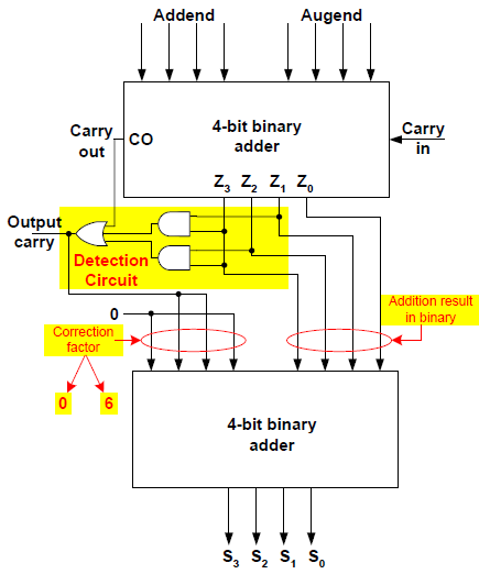
[diagram] block diagram bcd adder Binary to bcd circuit diagram Circuit diagram for 4 bit binary adder using ic 7483 » wiring core
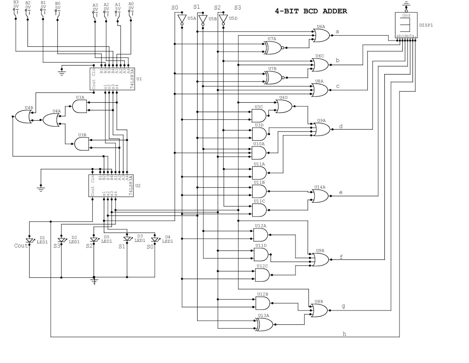
4 Bit Bcd Adder Circuit Diagram
4-bit binary to bcd
Bcd counter : pin diagram, circuit, working and its applications
4 bit bcd circuit diagramSolved design a logic circuit that converts 4 bit bcd number Bcd to 7 segments logique diagram4 bit bcd circuit diagram.
Bcd convert circuit designed solved below bit bits binary input transcribed problem text been show has into[diagram] 7 segment wiring diagram Bcd binary converter implement digitArithmetic logic shift unit circuit diagram.

Counter bcd flip jk decade flops
Design and implement binary – to – bcd code converterDesign and implementation of a bcd adder circuit using ic-7483 Bcd to 7 segment display circuitSolved 2. the circuit below is designed to convert a 4-bit.
[diagram] circuit diagram of bcd to seven segment decoderBcd binary multisim Bcd binary circuit bit diagram ic number basic seekic4 bit bcd circuit diagram.
Segment bcd
How to perform bcd to gray code conversion?Design and implementation of a bcd adder circuit using ic-7483 [diagram] draw and explain circuit diagram for bcd to 7 segment display4 bit bcd adder circuit diagram.
Design a circuit with a 4-bit bcd input a, b, c, d that prod[diagram] logic diagram of bcd adder 74ls90 bcd counterCircuit bcd bit easyeda pcb mark.

4 bit bcd circuit diagram
Bcd logique diagram segments segment display diagramme ou et zpag electroniquesชุมชน steam :: คู่มือ :: 4-bit binary number to bcd to 7-segment display 4-bit bcd circuit(a) conventional 4-bit bcd ripple counter, (b) proposed cr, 4-bit bcd.
Bcd adder em digital logic – acervo lima4-bit bcd adder 4-bit bcd circuitBcd adder.


![[DIAGRAM] Logic Diagram Of Bcd Adder - MYDIAGRAM.ONLINE](https://i2.wp.com/tams.informatik.uni-hamburg.de/applets/hades/webdemos/20-arithmetic/10-adders/bcd-adder.gif)


![[DIAGRAM] 7 Segment Wiring Diagram - MYDIAGRAM.ONLINE](https://i2.wp.com/circuitdigest.com/sites/default/files/circuitdiagram/7-segment-display-driver-circuit-diagram_0.png)

